Keeping an older organ maintained properly can be very rewarding, although sometimes challenging, especially
when many of the original vendors have gone out of business. Because some of the repairs required of any installation
require parts that are no longer made, the technician must seek creative solutions.
Problem Statement
A few years ago Bob Trousdale faced the problem of repairing several large scale chimes at Plummer Auditorium
in Fullerton, California. Each of these chimes had a vertical crack about six inches long starting at the top end near the
plug and catgut hanger, adversely affecting the sound quality. Bob had asked members of the Plummer crew if anyone
knew of a solution to this problem. There had been a few articles published in Theater Organ magazine, as well
as the Glue Pot newsletter, but these repair schemes yielded various results, from Pretty Good to Not so Good.
History
There have been many attempts at restoring the sound of cracked chimes. Hose clamps have been installed on
the crack to pull it closed, but this does not work completely. The tone is not fully restored, and a low frequency
undulation can result. Filling the crack with epoxy and wedges has been tried, although this still permits a discontinuity
along the crack surface, which interferes with the vibrations.
The original chimes used by Wurlitzer and other makes were supplied by J. C. Deagan of Chicago. They were made
of nickel-plated brass, and they tended to crack during the 60 to 70 years of hard use. The typical crack occurs
at the end of the tube in a longitudinal direction, and tends to dull and shorten the strike tone by interfering
with vibration propagation.
Physics
A possible cause of cracking could be found in the way the tubes are formed during manufacture. The better grades
of chimes - Class A, B, and C were drawn, but the Class R tubes were rolled from a brass sheet, shaped into a tube
and joined at a seam. Solid plugs are then pressed into one or both ends, which affects the tone quality of the
chime. This added mass acts to lower the pitch of the fundamental and the first few harmonics, effectively stretching
the perceived pitch to one that is more pleasant to the ear. Pressing the plugs into the tube with an interference
fit is necessary to match the impedence between the tube and the plug, making the assembly behave like one solid
system. However, this interference fit causes a tensile hoop stress in the tube, much like that found in a rain
barrel full of water, where the weight of the water places a bursting force in the outward direction. Steel hoops
are usually installed around the circumference to contain these outward forces.
Local stress at the tip of a crack is extremely high, and easily exceeds the tensile strength of the base metal,
causing the crack to propagate quickly once formed. In addition, microscopic imperfections in the base metal and
seams made during manufacture cause local stress risers, which encourage the formation of cracks. Furthermore,
the typical chime is struck repeatedly by a hammer, encouraging crack growth.
Previous Solutions
One method of chime tube repair has been to cut off the offending part and turn the tube into a higher note.
This is not usually the best way to solve the problem for two reasons: First, the scale of the trimmed tube usually
won't match the rest of the original set, and second, there are no guarantees of finding a larger set that is close
in scale.
Solution and Metallurgy
We have found that the chimes can be repaired by welding with a TIG welder (Tungsten Inert Gas). Silicon Bronze
rod is used as the filler metal because it closely matches the parent metal mechanical properties, and it has very
good welding characteristics.
First, a bit about brass. Made of varying parts of copper and another element, such as zinc or sometimes silicon,
brass is easy to machine and finish. The zinc contained in the brass will vaporize at an amazingly low 1,663 degrees
F, and is very toxic, so you'll want to have adequate ventilation or the proper respirator for metal vapors.
The chime shown in this article is cracked at the bottom end, and has a recessed bottom plug inserted. Double
plugged tubes usually have a very small hole drilled to allow for pressure escape during manufacture.
The Repair Process
Remove the catgut hanger if it is near the weld site.
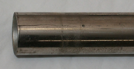
Fig. 1. Crack in tube before preparation.
Mark the radial location of the top plug if welding that end, since it will need to be realigned back to
its original position after the welding. A small pair of punch marks will suffice. If removing the bottom plug,
you will need to measure the depth if recessed, then drill and tap a hole through it in order to thread in a removing
tool. I use a tap of 1/4"-20 size, then insert a bolt for knocking it out with vise grips and a hammer.
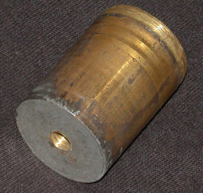
Notice the silver paint on the tube in Fig. 2 - electroplating does not work very well in a recessed hole, so the
factory painted the area to make it blend with the rest of the nickel finish.
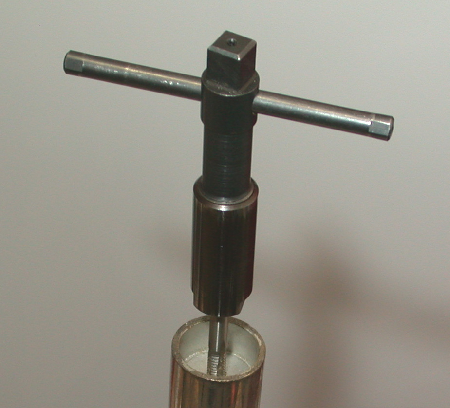
Fig. 2: Tapping the Bottom Plug
Remove the plug by first heating the end of the tube with a propane torch. While the tube is hot, drive out
the plug by placing a long bar in the chime from the other end, and gently tapping it with a hammer, or if pulling
the Bottom Plug, extract with a threaded puller. Because there is an open crack in the tube, the interference fit
of the plug will be reduced, and at this point the plug may simply fall out.
Fig. 3: The Bottom Plug
Using a fine file, gently file off the nickel plating on the outside of
the tube back to about 3/4 inch away from the weld area. During the welding
process the arc temperature can reach 6,000 deg. F, hot enough to vaporize
almost all metals. Any plating should be removed around the weld area to
prevent contamination of the weld, and also to limit any heavy metals from
being vaporized into the air, posing a health hazard.
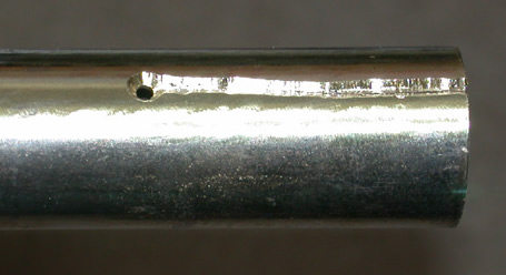
Drill a 1/8" hole in the chime about 1/2 of an inch beyond the last
visible part of the crack. This gives the crack a "friendly" place
to end its travel, and will prevent further propagation during welding and while
in use later.
Chamfer the crack to about 80% depth at 45 degrees using a
rotary file, such as a Dremel tool or die grinder. This will provide for
proper weld penetration.
Place a hose clamp at the end of the tube and tighten it to close the crack completely.
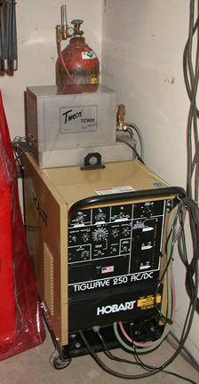
TIG weld the crack closed using Silicon Bronze rod. I use a Hobart TigWave 250 with the following settings:
DC Electrode Negative
Argon 20 CFH
150 Amps current
AC balance set to dc welding
AC arc stabilization on
Crater fill on - 1 sec
Remote amperage control on
Postflow 3-5 sec
Electrode - 2% thoriated, 1/16" diameter
Silicon bronze rod - 1/16" diameter
Positive ventilation of the shop (poison fumes) and a filter mask
Fig. 5: The Welder
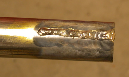
Fig. 6 - Completed weld bead
After the weld cools, dress the interior bore using a rotary file. Before driving the plug back in, this area
will need to be smooth and as close to the original bore as possible - do not increase the diameter!
Heat the tube end with a propane torch and drive the plug in the same
position as it was originally. If inserting a Bottom Plug, replace it to the
same depth as measured earlier.
The bottom plug will need to have its threaded hole filled with the same
amount of mass as was removed during drilling and tapping. Countersink the
bottom of the the hole to accept a brass flathead screw. Place a drop of
Locktite on the screw threads to keep the screw from vibrating loose, and
install to a tight fit.
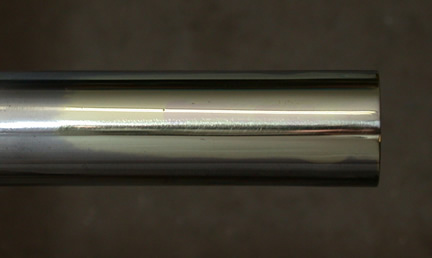
File, sand and polish the weld area. This step is best done after replacing
the plug because the interference fit will cause a local waviness in the tube,
which will need to be polished out again. If you really want a clean tube,
polish the remainder with Chrome cleaner, clean off with a surface prep, then
clear coat with lacquer.
Fig. 7 - Bead filed off and tube polished.
Replace the catgut hanger if it was removed.
Check for sound quality.
Results
The completed chime has the tone restored, and matches the timbre of the other tubes in the set. The appearance
of the chime reveals that the repair site is visible, but not overly noticeable. The nickel plate has been removed
in the area adjacent to the welding, and the underlying brass has been polished. This may not be a problem since
many chimes are hung vertically with the tops hidden by the hammer action, so your handy-work might be covered
up in the end. The actual weld bead can be distinguished by its color, which has slightly more copper in it than
the native brass in the tube, since some of the zinc has boiled off during welding.
Fig. 8 - Installed Chime Tube back home with the others
Conclusion
To date we have about 10 chimes in service, the longest one being in use since 1997 with no observable failure.
The projected service life is not known, but it seems that the repaired area should be stronger than the original
seam.
Many thanks to Bob Trousdale, John Ledwon and Al Sefl for their help in preparing this article.
References:
Mark's Standard Handbook for Mechanical Engineers - 8th Edition
Baumeister, Avallone, Baumeister
McGraw-Hill
ISBN 0-07-004123-7
Welding Handbook
Finch, Richard, & Monroe, Tom
HP Books
ISBN 0-89586-257-3
The Science of Sound
Rossing, Thomas D.
Addison-Wesley Publishing Co.
ISBN 0-201-15727-6